How to Prevent Ice Dams
To prevent Ice Dams on Roofs, Gutters, and Downspouts BriskHeat has designed and developed an easy-to-install De-Icing Kit; designed to prevent the formation of ice dams on rooftops by using an electric self-regulating roof heat cable system. The roof heating heat cables melt away excessive ice and snow (ice dam) to ensure proper draining and prevent structural damage.
The SpeedTrace Roof and Gutter Kit is safe to leave installed year-round, but remember to unplug the heating cable when temperatures are warm and the cable doesn’t need to be running. Even more, you may use the Thermo-Cube Temperature Controlled Outlet Adapter for worry-free on/ off control so that the cable is only running when needed.
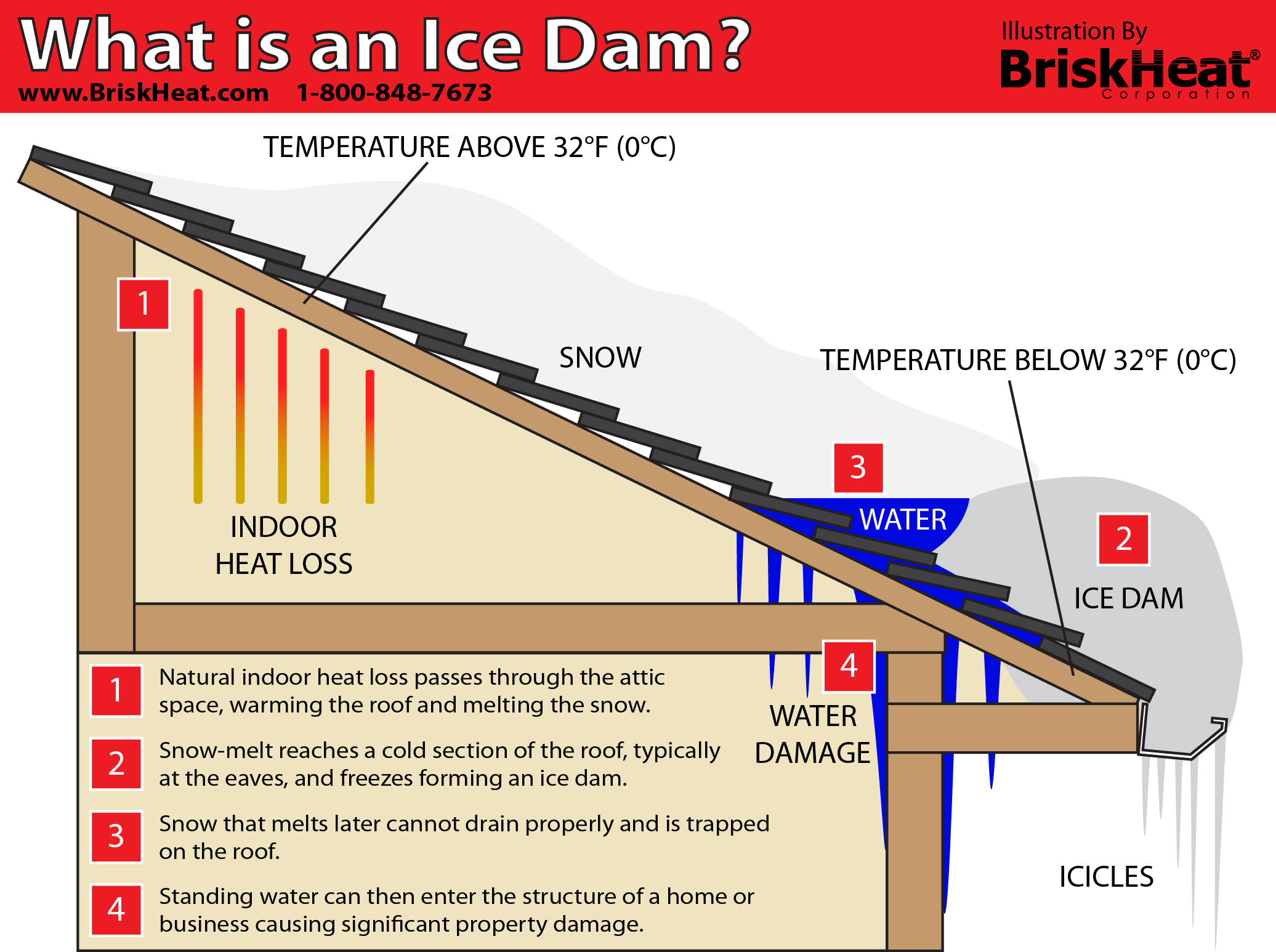
What is an Ice Dam?
- Naturally, some heat loss occurs through an attic. As even a small amount of heat passes through the attic space it warms the roof.
- Snow on the roof melts and runs under the insulating blanket of snow, until it reaches a cold section of the roof and freezes, beginning the formation of an ice dam.
- More snow melts and cannot drain properly. Snow melt water then gets trapped, creating standing water on the rooftop.
- Standing water then can enter a home or business by penetrating through roofing materials causing significant property damage.
Step 1: Selecting Heating Cable
ce Dams are Ice buildups that form on a rooftop, normally at the edge of the roof, due to the inherent temperature differences between heated spaces and roof overhangs. This ice build up then prevents melting snow (water) from properly draining off of the roof. The water then backs up behind the ice dam and can create leaks into homes and cause damage to walls, ceilings, insulation, and other areas.
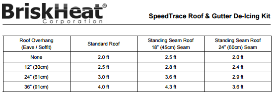
Use the equation and table below to calculate the required heating cable length:
Cable Required for Roof = (R x M) + G + D
(R) Roof Edge Length (linear length of roof to protect)
(M) Multiplier from table below
(G) Gutter Length
(D) Downspout Length (X2 if heating cable returns back to gutter) Heating Cable Length Required [Round Up to the closet kit size]
Example (Standard Roof):
Measurements:
Roof Edge Length: 16ft (4.9m)
Roof Overhang: 12” (30cm)
Gutter Length: 16ft (4.9m)
Downspout Length (no return): 15ft (4.6m)
Equation:
Roof Edge: 16 ft (4.9m) x 2.5 (from table) = 40ft (12.2m)
Gutter Length: + 16 ft (4.9m)
Downspout Length: + 15 ft (4.6m)
Required Cable Length = 71ft (21.6m) = 75ft (22.9m) Kit [Rounded Up]
Tips for Calculating Roof Heating Cable Length
When calculating downspout length, if the downspout is at the end of a run, measure the full length of the downspout and use that value.
When calculating downspout length, if the downspout is not at the end of a run and heating cable must return to the gutter, double the length of the downspout to determine the length of cable to install. You will need to loop the cable back up the downspout to continue along the gutter.
For downspouts that extend below ground, heating cable should extend below the frost line if tied into a drainage system.
If installing the cable in a gutter at the very end of a run, do not allow the end of the heating cable to stick out in the air at the end of the downspout. Instead loop the cable back up the downspout for 1ft (0.3m) and connect with a cable tie if possible.
For roof drains leading into a heated area, a loop of heating cable is installed to a typical depth of 3.3 ft (1m).
For valleys, run the heating cable two thirds of the way up and back down the valley. You must add this value to your total cable length calculation.
For custom length Heating Cable needs, be sure to checkout our:
Step 2: Choosing When to Install
Install the SpeedTrace Roof & Gutter Kit when the conditions are warm, dry, and safe. The best time to install is in advance of cold temperatures arriving. Warmer temperatures will also allow standard shingles or shakes to set or reseal after installation.
When using an RTV adhesive, follow the application directions provided by the RTV manufacturer. Be sure to allow time for the RTV to cure and set without being interrupted by inclement weather.
ROOF & GUTTER REQUIREMENTS
Suitable For:
- Standard pitched roof with or without a gutter
- Standard roofing materials including shingle, shake, rubber, tar, wood, metal and plastic roofs
- Gutters and downspouts made from standard materials including metal and plastic
Not Suitable For:
- Flat roof tops
- Slate, stone, ceramic, composite (tar and gravel) roofs
Step 3: Installation Preparation
Before getting starting with installing your BriskHeat Roof & Gutter Kit:
- Carefully remove any existing cables, clips, and roof clips from the roof, gutter, and downspouts.
- Clean the roof, gutter, and downspouts of leaves and other debris.
- Check the roof, gutter, and downspouts for sharp edges and file them down or repair them as necessary.
- Test the heating cable to make sure it’s functioning properly. Unwind the cable and then plug it in. Wait 5 minutes then touch the cable. The cable should feel slightly warm to the touch.
- Unplug the cable before installing.
Choose a Starting Point
Select a starting point for the heating cable near a GFCI (15 amp minimum) power outlet. The outlet should be protected from inclement weather.
Draw Diagram of the Cable Plan Arrangement and Roof Clip Placement
Using the roof, gutter, and downspout measurements and the arrangements listed previously, sketch the cable arrangement and roof clip placement on paper.
Mark the Roof Pattern with Chalk
After sketching it on paper, it’s recommended that you mark the roof with chalk to match the drawing for easy installation. The markings should indicate where the cable and roof clips will need to be installed.
Installation Items Needed:
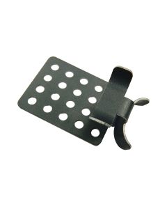
- Roof Clips - Buy Now
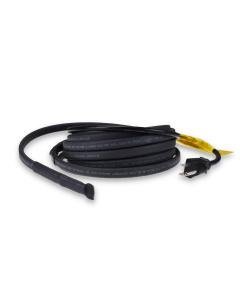
- SpeedTrace Heating Cable - Buy Now
- RTV Adhesive for Roofs - Buy Now
- Nails & Hammer OR Screws & Screwdriver or Drill
- Downspout Gutter Hangers / Brackets (if Roof has a Gutter) - Buy Now
- Cable ties (for installation in gutters)
Step 4: Select Roof Installation Type
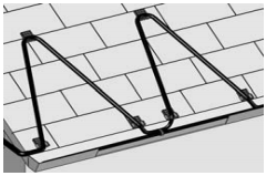
1. Standard Pitched Roofs with Gutters
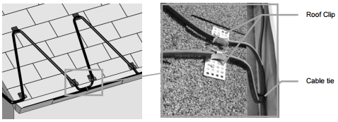
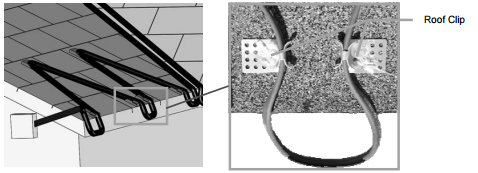
Cable Placement: The cable will be installed in a triangular zig-zag pattern with the lower corner points overhanging the edge of the roof into the gutter and almost touching the bottom of the inside of the gutter.
Clip Placement: Use 1 roof clip at each top corner point of the zig-zag and 2 clips at each bottom corner point.
2. Standard Pitched Roofs without Gutters
Cable Placement: The cable will be installed in a triangular zig-zag pattern with the lower corner points overhanging the edge of the roof.
Clip Placement: Use 1 roof clip at each top corner point of the zig-zag and 2 clips at each bottom corner point.
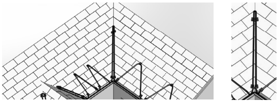
3. Installation on Roof Valleys
Cable Placement: Run the heating cable 2/3rds of the way up and down the valley.
Clip Placement: Use 4 roof clips to secure the cable on the valley. Use 2 roof clips at the top corner point on each side of the run, and 2 roof clips at the bottom corner point on each side of the run.
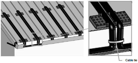
4. Standing Seam Metal & Plastic Roofs
Cable Placement: Run the heating cable along the standing seam to the tracing height specified in the chart below. Then run the cable to the edge of the roof. Where the two ends of the cable meet at the base of each seam, they will be connected with a cable tie as shown.
Clip Placement: Use 2 roof clips at the top corner points and 2 roof clips at the lower bottom corner points along the standing seam. Where the 2 ends of the cable meet at the base of each seam, they will be connected with a UV-resistant cable tie
Step 5: Install Heating Cable on Roof
1. Determine the heating cable layout and clip placement according to the Cable Pattern Arrangement and Roof Clip Placement
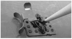
2. Following the RTV adhesive manufacturing instructions, apply RTV adhesive appropriate for your roof, to the back side of the roof clip where the nail or screw will be used.
3. Determine the heating cable layout and clip placement according to the Cable Pattern Arrangement and Roof Clip Placement
4. Determine the heating cable layout and clip placement according to the Cable Pattern Arrangement and Roof Clip Placement
5. Allow the RTV adhesive to cure and dry before installing the cable. Refer to the RTV adhesive instructions for the cure time of the adhesive used.
6. Repeat this process. Wait for all of the adhesive on the roof clips to cure before continuing with the installation of the cable.
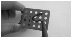
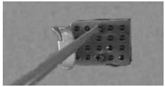
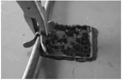
7. After the RTV adhesive has cured, install the heating cable between the clip clamps following the Cable Pattern Arrangement and Roof Clip Placement diagrams. Use pliers to close the clamps gently around the heating cable. Do not crush the heating cable.
8. Run the cable from the starting point and use a roof clip to connect the cable to the edge of the roof.
9. If chalk lines were made, follow the chalk lines in the standard zig-zag pattern and attach the cable to the roof with the roof clips. The lower corner points of the cable should hang over the edge of the roof.
10. Determine the heating cable layout and clip placement according to the Cable Pattern Arrangement and Roof Clip Placement
Step 6: Check the Installation
Prior to plugging in, check to be sure the heating cable is free of mechanical damage (cuts, clamps, etc.).
Junction boxes should be inspected for water or evidence of previous water leaks. If moisture is present, the box should be restored to dry conditions and the cause of the leak should be eliminated.
Functionality of overcurrent protection devices should be checked.
Optional Recommended Accessory
Thermo-Cube Thermostatically Controlled Outlet Perfect for worry-free operation all year long. Thermo Cube is a device which, when plugged into a standard GFCI (15 amp minimum) electrical outlet, automatically turns power on and off to any device plugged into it based upon ambient air temperatures. The Thermo Cube will automatically turn on power when air temperature falls below approximately 35°F (2°C) and will turn off the power when the temperature rises above approximately 45°F (7°C).